How many nodes?
Minimum viable OKD cluster is three nodes. That’s driven by etcd — it needs a quorum (majority of members healthy). Three members = you can lose one. Two = you can lose none. One = not distributed.
Three nodes also gives you meaningful Ceph replication. Replication factor 3 means each piece of data lives on three nodes. Lose one, data is still on the remaining two while Ceph rebalances.
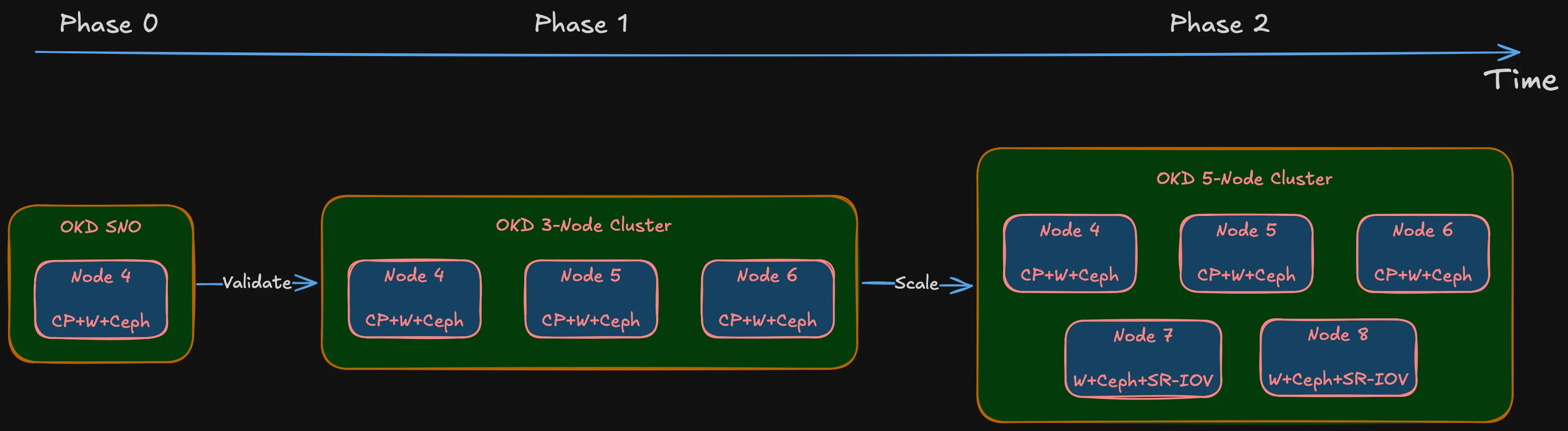
The plan is phased:
Summary (Deployment phases)
- Phase 0: OKD Single Node (SNO). Full OKD deployment on one machine to validate hardware, storage, and networking. If something fundamental doesn’t work — NIC incompatibility, BIOS issue, storage controller conflict — better to find out on one node than three.
- Phase 1: Three nodes (Nodes 4, 5, 6). Combined control plane + worker. Each node in etcd, running OKD control plane, accepting workloads. Three nodes, three failure domains.
- Phase 2: Five nodes (add Nodes 7, 8). Worker-only nodes. Control plane stays on Nodes 4-6. More compute, more Ceph OSDs, SR-IOV networking for IoT/DMZ passthrough.
Why not go straight to five? Phase 0 validates hardware. Phase 1 validates architecture. Phase 2 scales it. Buying five machines before validating on one is exactly the impulse-purchase approach this series avoids.
Note (Node numbering)
Starts at Node 4 because Nodes 1-3 are existing infrastructure — the OptiPlex 7050 Micro (Node 1) and reserved IDs for future lightweight roles.
Sizing: CPU and memory
OKD’s control plane isn’t lightweight. API server, etcd, controller manager, scheduler, OAuth, image registry, monitoring stack (Prometheus, Alertmanager, Grafana), ingress controllers — all running on nodes that also handle workloads.
Red Hat’s minimum for an OpenShift control plane node: 4 vCPUs, 16 GB RAM. That’s the spec where the cluster boots but Prometheus gets OOMKilled as soon as you deploy something real.
For combined control plane + worker with Ceph OSDs on the same node, I need more:
CPU: 8 cores / 16 threads. Room for the control plane, Ceph OSD processes (one per disk, two or three per node), monitoring, and actual application pods. Desktop 8-core processors are widely available in SFF chassis on the used market — specific model is a BOM decision.
Tip (Memory sizing)
64 GB minimum, upgradeable to 128 GB. Each Ceph OSD uses ~4 GB RAM. Two or three OSDs per node = 8-12 GB just for storage. OKD control plane and monitoring take another 12-16 GB. That leaves 36-44 GB for workloads and VMs — okay, but not extravagant. 32 GB would choke once VMs enter the picture.
The design requires four DIMM slots. Start with 2 x 32 GB (64 GB) for Phase 1. Once the cluster is stable and I can see actual memory pressure under real workloads, the other two slots can take another 2 x 32 GB to hit 128 GB. The upgrade decision gets made on data, not guesswork.
Why small form factor?
The chassis choice is a BOM decision. But the design sets clear requirements:
Definition (Chassis requirements)
- Four DIMM slots — 64 GB at launch, path to 128 GB
- At least one PCIe x8 (Gen 3) slot — for a dual-port 10 Gbps SFP+ NIC. Most important expansion slot. Without it, storage networking is 1 Gbps and Ceph performance tanks
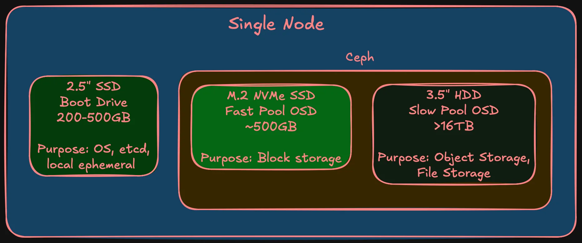
- One M.2 NVMe slot — fast Ceph OSD tier
- One 2.5” SATA bay (or second M.2) — boot drive, separate from Ceph
- One 3.5” drive bay — slow Ceph OSD tier, large HDD. This alone rules out micro/ultra-compact form factors
- Desktop-class TDP — 65W, not 150W+
SFF doesn’t rack-mount without shelves, which adds physical planning (covered later). But the power/noise/cost trade-off is worth it for a homelab that coexists with a household.
Failure domains
In cloud, failure domains are availability zones — entire data centers. In a homelab, every node sits in the same room, same power circuit, same shelf. Technically, all nodes could be in a single failure domain and that would be honest.
But that defeats the purpose. The main reason to set up separate failure domains in a homelab is to learn how they actually work — how Ceph distributes replicas across them, how pod anti-affinity interacts with topology constraints, how OKD handles node failures within failure domain awareness. One node per failure domain gives the most production-realistic behavior at homelab scale.
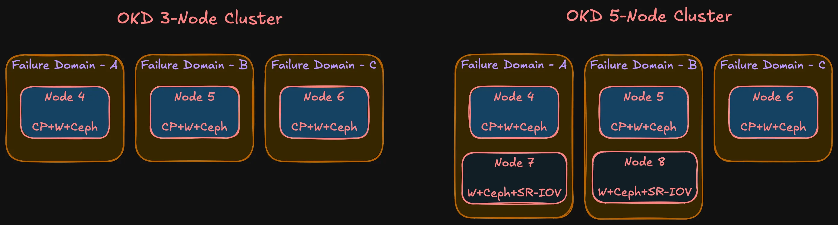
With three nodes and three failure domains:
- etcd: Three members, quorum survives one node loss
- Ceph: Replication-3, one replica per FD. Data survives one node failure, Ceph rebalances from remaining replicas
- OKD control plane: Three API server instances. Pod disruption budgets prevent quorum violations during rolling operations
- Workloads: Anti-affinity spreads replicas across FDs. One node loss = at most one-third of capacity
Phase 2 doesn’t change the model — still three FDs. Nodes 7 and 8 join FD-A and FD-B respectively. Some asymmetry (FD-C has one node, others have two), but the important thing is no single FD holds a majority of etcd members or Ceph replicas.
Node roles
| Node | Phase | Roles | Failure Domain |
|---|---|---|---|
| Node 4 | Phase 1 | Control plane + Worker + Ceph OSD | FD-A |
| Node 5 | Phase 1 | Control plane + Worker + Ceph OSD | FD-B |
| Node 6 | Phase 1 | Control plane + Worker + Ceph OSD | FD-C |
| Node 7 | Phase 2 | Worker + Ceph OSD | FD-A |
| Node 8 | Phase 2 | Worker + Ceph OSD | FD-B |
What’s not decided yet
Note (Deferred to Bill of Materials)
- Chassis make and model — design defines requirements. Multiple vendors meet this. Choice depends on market availability and compatibility.
- HDD model and capacity — need large HDDs for slow Ceph tier. Depends on pricing and availability.
- DDR4 frequency — various speeds work. Difference between DDR4-2400 and DDR4-3200 is negligible for this workload.
- NIC model — The design requires a 10 Gbps NIC in each node. Connector type (SFP+, RJ45 10GbE), port count, and specific model are procurement decisions for the BOM post.
These aren’t gaps — they’re the boundary between design and procurement. The design says “64 GB DDR4, 4 DIMM slots, 10 Gbps NIC.” The BOM says which exact module, from where, at what price.
Summary
Summary (Compute design at a glance)
- Phase 0 (SNO) validates hardware → Phase 1 (3 nodes) validates architecture → Phase 2 (5 nodes) scales
- Combined control plane + worker on Phase 1 nodes; Phase 2 adds workers
- 8 cores / 16 threads per node
- 64 GB RAM (2 x 32 GB), upgradeable to 128 GB (4 DIMM slots)
- Three storage tiers: boot SSD, fast NVMe (Ceph), slow HDD (Ceph)
- 10 Gbps interface for storage networking
- 1 Gbps RJ45 for management
- SFF form factor — power, noise, cost
- Three failure domains in both phases
- OKD on SCOS with Rook-Ceph
Every decision traces back to the requirements from the why post. Hardware specifics come in the BOM post. Next up: network architecture — because none of this works without the right connectivity between nodes.