The network design post defined VLANs, firewall policy, and device requirements. This is where that design hits real hardware — CCR2004 router and CRS317 switch, factory reset to a working VLAN-segmented network. One node, two VLANs, two devices. Everything else waits.
Summary (What's in scope)
- VLAN 5 (Frontnet) — management, SSH, DHCP, DNS. OKD API and ingress VIPs also live here for SNO.
- VLAN 10 (Backnet) — storage network. Fully isolated, no internet, no inter-VLAN routing.
- Factory reset on both devices — clean slate.
Note (What's deferred)
VLAN 20 (IoT), VLAN 30 (Guest), VLAN 40 (DMZ), LACP bonds, jumbo frames, SR-IOV. All added when the endpoints that need them exist.
Wait — the design said VLAN 1
Yes. The network design post used VLAN 1 as the Frontnet/management VLAN. That’s the natural choice — VLAN 1 is the default PVID on every port, and every MikroTik guide uses it.
It didn’t work.
With VLAN filtering enabled on both the CCR2004 and CRS317, every device behind the CRS317 — the Mac mini, anything on the storage network — lost connectivity. DHCP stopped, ARP stopped, pings timed out. Devices directly connected to the router’s RJ45 ports worked fine. The problem was specific to the 10G trunk between the two devices.
After hours of troubleshooting — packet captures on every interface, toggling HW offload, swapping SFP+ ports, factory resets on both — the root cause: the Marvell Prestera switch chip in the CRS317 doesn’t reliably handle VLAN 1 when carried tagged on a trunk. ARP broadcasts flood correctly, but unicast ARP replies and DHCP offers get silently dropped before reaching the destination access port.
VLAN 1 has special behavior in 802.1Q — it’s the “default” VLAN, and some hardware treats it differently in the forwarding pipeline. The Marvell 98DX8216 in the CRS317 is one of those cases.
Danger (Lesson learned)
Avoid VLAN 1 on MikroTik trunk links, especially between devices with different switch chips (CCR2004 uses Marvell 88E6191X, CRS317 uses Marvell 98DX8216). Use any other VLAN ID. This costs nothing and avoids a whole category of hard-to-debug forwarding issues.
The fix: don’t use VLAN 1. I picked VLAN 5. Set it as PVID on all access ports, carry it tagged on the trunk. Everything works immediately.
Physical cabling
Before any configuration:
| From | Port | To | Port | Cable |
|---|---|---|---|---|
| ISP bridge | — | CCR2004 | sfp-sfpplus1 | RJ45 SFP+ module |
| CCR2004 | sfp-sfpplus2 | CRS317 | sfp-sfpplus1 | DAC 0.3m |
| CCR2004 | ether1 | Synology NAS | LAN 1 | RJ45 |
| CCR2004 | ether3 | WAP | ether1 | RJ45 |
| CCR2004 | ether4 | DNS server | eth0 | RJ45 |
| CCR2004 | ether8 | Node 4 | onboard NIC | RJ45 |
| CCR2004 | ether13 | CRS317 | ether1 | RJ45 (OOB mgmt) |
| CRS317 | sfp-sfpplus2 | Node 4 | CX4121C port 1 | DAC |
| CRS317 | sfp-sfpplus12 | Mac mini | 10G NIC | RJ45 SFP+ module |
Node 4’s second CX4121C port (sfp-sfpplus3) is reserved for LACP bonding later. Ports for Nodes 5-8 are reserved but disabled.
Factory reset — both devices
Both devices must start clean. The MikroTik default config creates a bridge with all ports — those leftovers will conflict with VLAN filtering.
# CCR2004:/system reset-configuration no-defaults=yes skip-backup=yes
# CRS317:/system reset-configuration no-defaults=yes skip-backup=yesAfter reset, the device has no IP, no bridge, nothing. Reconnect via MAC Winbox.
CCR2004 router configuration
The CCR2004 is the edge router — NAT boundary, DHCP server, inter-VLAN firewall, gateway for everything.
System basics
/system identity set name="gw-home"/system clock set time-zone-name=Europe/Warsaw
/ip serviceset telnet disabled=yesset ftp disabled=yesset api disabled=yesset api-ssl disabled=yesset winbox address=192.168.1.0/24
/system ntp client set enabled=yes/system ntp client servers add address=pool.ntp.orgWhat is bridge-lan and why does everything go into it?
In MikroTik, a bridge is a virtual switch — it connects physical ports at L2. Without one, each port on the CCR2004 is isolated. Devices on ether1 can’t talk to devices on ether8. Adding ports to bridge-lan creates a single switching domain — like plugging everything into the same unmanaged switch. VLAN filtering on top of that bridge creates the separation: ports tagged for VLAN 5 can only talk to other VLAN 5 ports, VLAN 10 only to VLAN 10, etc. If this isn’t clicking, the MikroTik VLAN videos at the bottom walk through bridges and vlan-filtering step by step.
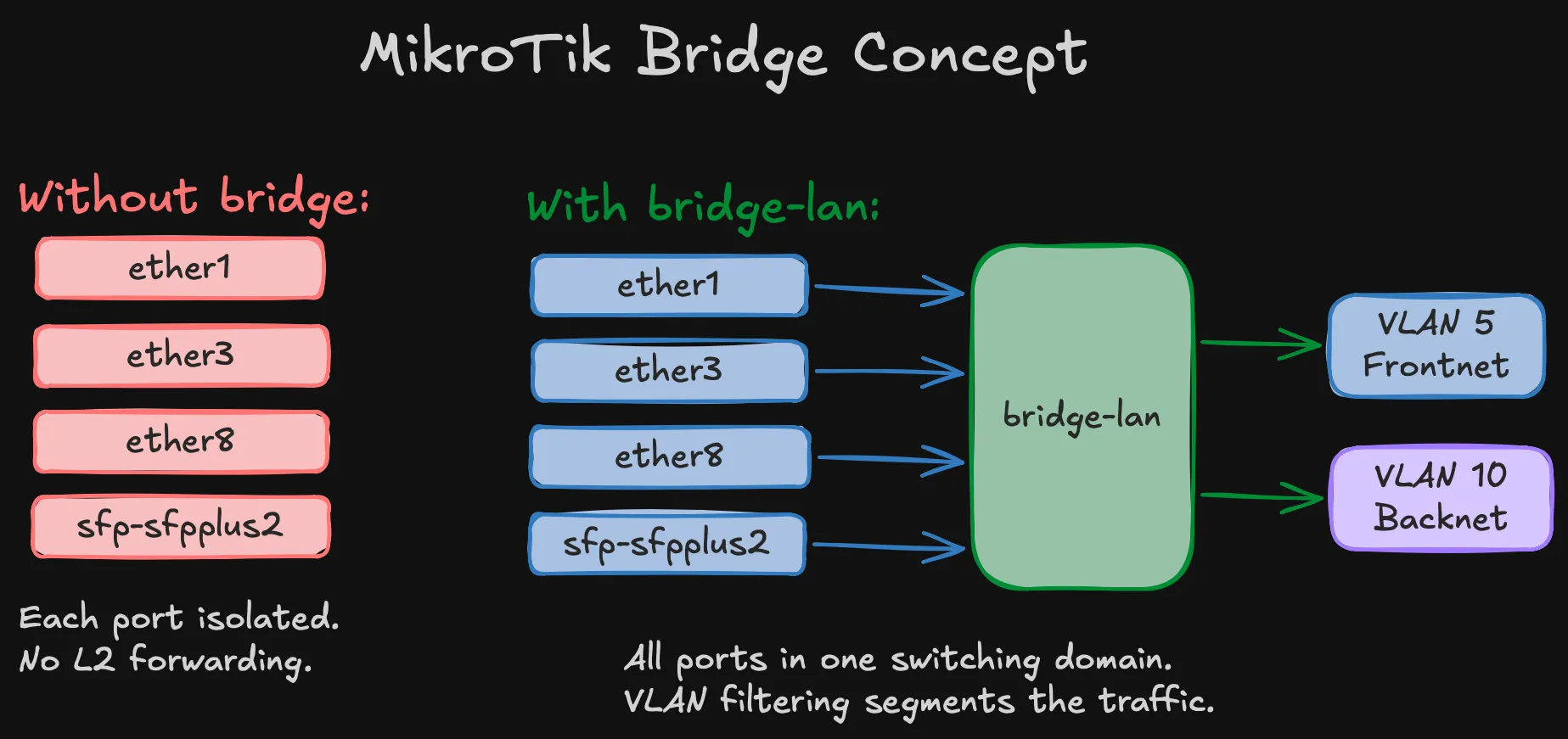
The WAN interface (sfp-sfpplus1) stays out of the bridge on purpose. It’s a routed interface — traffic between LAN and WAN goes through the router’s IP stack (NAT, firewall), not through L2 switching.
Bridge and ports
/interface bridge add name=bridge-lan \ vlan-filtering=no \ pvid=5 \ comment="LAN bridge — enable vlan-filtering LAST"Warning (vlan-filtering=no is deliberate)
The bridge is created with filtering off and enabled as the very last step, after everything else is verified. Enabling it with incorrect VLAN table entries will silently drop frames and lock you out. Every MikroTik VLAN guide warns about this. Every homelab builder learns it the hard way.
# Synology NAS (ether2 reserved for future LACP bond)/interface bridge port add bridge=bridge-lan interface=ether1 pvid=5 comment="Synology"/interface bridge port add bridge=bridge-lan interface=ether3 pvid=5 comment="WAP"/interface bridge port add bridge=bridge-lan interface=ether4 pvid=5 comment="DNS-server"# Nodes 1–3 (legacy / future)/interface bridge port add bridge=bridge-lan interface=ether5 pvid=5 comment="Node-1"/interface bridge port add bridge=bridge-lan interface=ether6 pvid=5 comment="Node-2"/interface bridge port add bridge=bridge-lan interface=ether7 pvid=5 comment="Node-3"# Node 4 (active for SNO)/interface bridge port add bridge=bridge-lan interface=ether8 pvid=5 comment="Node-4"# Nodes 5–8 (ports in bridge, nothing plugged in yet)/interface bridge port add bridge=bridge-lan interface=ether9 pvid=5 comment="Node-5"/interface bridge port add bridge=bridge-lan interface=ether10 pvid=5 comment="Node-6"/interface bridge port add bridge=bridge-lan interface=ether11 pvid=5 comment="Node-7"/interface bridge port add bridge=bridge-lan interface=ether12 pvid=5 comment="Node-8"# CRS317 OOB management/interface bridge port add bridge=bridge-lan interface=ether13 pvid=5 comment="CRS317-OOB"# 10G trunk to CRS317/interface bridge port add bridge=bridge-lan interface=sfp-sfpplus2 pvid=5 comment="Trunk-to-CRS317"Every LAN port gets PVID=5. The WAN interface (sfp-sfpplus1) stays out of the bridge — it’s routed.
VLAN table
# VLAN 5 — Frontnet: tagged on bridge + trunk, untagged on access ports/interface bridge vlan add bridge=bridge-lan vlan-ids=5 \ tagged=bridge-lan,sfp-sfpplus2 \ untagged=ether1,ether3,ether4,ether5,ether6,ether7,ether8,ether9,ether10,ether11,ether12,ether13
# VLAN 10 — Backnet: tagged on bridge + trunk only (storage ports are on CRS317)/interface bridge vlan add bridge=bridge-lan vlan-ids=10 \ tagged=bridge-lan,sfp-sfpplus2Two VLANs, two entries. IoT/Guest/DMZ added when needed.
VLAN interfaces and IP addressing
/interface vlan add name=vlan5-frontnet interface=bridge-lan vlan-id=5/interface vlan add name=vlan10-backnet interface=bridge-lan vlan-id=10
/ip address add address=192.168.1.1/24 interface=vlan5-frontnet comment="Frontnet gateway"/ip address add address=192.168.10.1/24 interface=vlan10-backnet comment="Backnet gateway"Important (No IP on bridge-lan)
The gateway IP lives on vlan5-frontnet, not on the bridge directly. This is required when using VLAN 5 instead of default VLAN 1 — the DHCP server and firewall rules reference vlan5-frontnet as the Frontnet interface.
The Backnet gateway exists for diagnostics only — you can ping storage IPs from the router. Storage nodes should never use 192.168.10.1 as default route.
DNS
DNS static records and OKD-specific entries (API VIP, wildcard ingress) are covered in the SNO validation post — they’re part of the OKD prerequisites, not the base network config.
DHCP
/ip dhcp-client add interface=sfp-sfpplus1 use-peer-dns=no use-peer-ntp=no \ add-default-route=yes comment="WAN DHCP"
/ip pool add name=pool-frontnet ranges=192.168.1.50-192.168.1.249
/ip dhcp-server add name=dhcp-frontnet interface=vlan5-frontnet \ address-pool=pool-frontnet lease-time=12h disabled=no
/ip dhcp-server network add address=192.168.1.0/24 gateway=192.168.1.1 \ dns-server=192.168.1.12 domain=home.lab ntp-server=192.168.1.1Warning (DHCP binds to vlan5-frontnet, not bridge-lan)
DHCP discovers arrive tagged as VLAN 5, so the server must listen on the VLAN 5 interface. Binding to bridge-lan means the server never sees the requests.
Pool: .50–.249. Static infrastructure: .2–.49. OKD VIPs: .253–.254. No DHCP on Backnet — storage is static only.
Firewall
/ip firewall filter# INPUTadd chain=input action=accept connection-state=established,relatedadd chain=input action=drop connection-state=invalidadd chain=input action=accept protocol=icmpadd chain=input action=accept in-interface-list=MGMTadd chain=input action=drop in-interface-list=WANadd chain=input action=drop
# FORWARDadd chain=forward action=accept connection-state=established,relatedadd chain=forward action=drop connection-state=invalidadd chain=forward action=accept in-interface=vlan5-frontnet out-interface-list=WAN \ comment="Frontnet → Internet"add chain=forward action=accept in-interface=vlan5-frontnet comment="Frontnet → any VLAN"add chain=forward action=drop in-interface=vlan10-backnet comment="Backnet: drop all"add chain=forward action=drop comment="Default drop"Important (Firewall references vlan5-frontnet, not bridge-lan)
Using bridge-lan would match traffic from all VLANs including Backnet, breaking isolation completely.
NAT — why masquerade?
Standard masquerade — rewrites source addresses from RFC1918 to the router’s public IP on the way out. Without it, nothing reaches the internet.
/ip firewall nat add chain=srcnat out-interface-list=WAN action=masqueradePort forwards for OKD (API on 6443, ingress on 443/80) are added when external access is needed — commented out for now.
Bogon protection
With ISP in bridge mode, the WAN has a public IP. Private source addresses showing up on that link are spoofed — drop them before they hit the firewall:
/ip firewall rawadd chain=prerouting action=drop in-interface-list=WAN src-address=192.168.0.0/16add chain=prerouting action=drop in-interface-list=WAN src-address=10.0.0.0/8add chain=prerouting action=drop in-interface-list=WAN src-address=172.16.0.0/12Warning (If your ISP router does NAT)
If your ISP router does NAT (not bridge mode) and gives the CCR2004 a 192.168.0.x address, remove the 192.168.0.0/16 rule — it would block all return traffic.
Hardening — locking things down
MikroTik ships with several services enabled by default that you don’t need and shouldn’t expose:
/ip neighbor discovery-settings set discover-interface-list=LAN/tool bandwidth-server set enabled=no/tool mac-server set allowed-interface-list=MGMT/tool mac-server mac-winbox set allowed-interface-list=MGMT/ip ssh set strong-crypto=yes- Neighbor discovery restricted to LAN — don’t announce the router on the WAN interface
- Bandwidth server off — it’s a built-in throughput testing tool, no reason to leave it running
- MAC Winbox restricted to MGMT (Frontnet only) — MAC-level management access from the WAN side would be a security hole
- Strong crypto for SSH — disables weak ciphers
Enable VLAN filtering — last step
/interface bridge set bridge-lan vlan-filtering=yesDanger (With VLAN 5, filtering must be on)
Unlike VLAN 1 setups where things partially work with filtering off, the Frontnet gateway IP lives on vlan5-frontnet — which only receives traffic when the bridge is actively tagging. Filtering off = dead network.
Verify immediately: ping 192.168.1.1 from any device.
What I just built
Quick recap of the CCR2004 config:
- Bridge — connects all LAN ports into one switching domain
- VLAN table — VLAN 5 (Frontnet) on all access ports, VLAN 10 (Backnet) tagged on the trunk only
- VLAN interfaces — gateway IPs on
vlan5-frontnetandvlan10-backnet, not on the bridge itself - DHCP — Frontnet only, bound to the VLAN interface. Static-only on Backnet
- Firewall — Frontnet can reach everything, Backnet is dropped, WAN is locked down
- NAT — masquerade for internet access
- Bogon protection — drops spoofed private addresses on WAN
- Hardening — unnecessary services disabled, SSH hardened, MAC Winbox restricted to management
CRS317 switch configuration
The CRS317 is pure L2. No routing, no firewall — just forwarding frames between the trunk and access ports at line rate.
System basics + OOB management
/system identity set name="sw-storage"/system clock set time-zone-name=Europe/Warsaw
# OOB management on ether1 — NOT in the bridge/ip address add address=192.168.1.200/24 interface=ether1 comment="OOB management"/ip route add dst-address=0.0.0.0/0 gateway=192.168.1.1/ip dns set servers=192.168.1.12Tip (OOB management is your safety net)
ether1 stays outside the bridge. If VLAN filtering breaks the bridge, you can still reach the switch at 192.168.1.200 through the router’s ether13. This saved the troubleshooting session that led to the VLAN 5 fix.
Disable unused ports
/interface set sfp-sfpplus3 disabled=yes comment="Reserved (Node 4 bond port 2)"/interface set sfp-sfpplus4 disabled=yes comment="Reserved (Node 5 storage)"/interface set sfp-sfpplus5 disabled=yes comment="Reserved (Node 5 bond port 2)"/interface set sfp-sfpplus6 disabled=yes comment="Reserved (Node 6 storage)"/interface set sfp-sfpplus7 disabled=yes comment="Reserved (Node 6 bond port 2)"/interface set sfp-sfpplus8 disabled=yes comment="Reserved (Node 7 storage)"/interface set sfp-sfpplus9 disabled=yes comment="Reserved (Node 7 SR-IOV)"/interface set sfp-sfpplus10 disabled=yes comment="Reserved (Node 8 storage)"/interface set sfp-sfpplus11 disabled=yes comment="Reserved (Node 8 SR-IOV)"/interface set sfp-sfpplus13 disabled=yes comment="Unused"/interface set sfp-sfpplus14 disabled=yes comment="Unused"/interface set sfp-sfpplus15 disabled=yes comment="Unused"/interface set sfp-sfpplus16 disabled=yes comment="Unused"Every unused port disabled and commented with its future purpose.
Bridge, ports, and VLANs
/interface bridge add name=bridge-fabric vlan-filtering=no pvid=5 \ comment="Storage fabric bridge — enable vlan-filtering LAST"
# Trunk to router/interface bridge port add bridge=bridge-fabric interface=sfp-sfpplus1 pvid=5 hw=yes# Node 4 storage — PVID 10, switch assigns VLAN tag/interface bridge port add bridge=bridge-fabric interface=sfp-sfpplus2 pvid=10 hw=yes# Mac mini/interface bridge port add bridge=bridge-fabric interface=sfp-sfpplus12 pvid=5 hw=yes
# VLAN 5 — Frontnet: tagged on trunk, untagged on Mac mini/interface bridge vlan add bridge=bridge-fabric vlan-ids=5 \ tagged=bridge-fabric,sfp-sfpplus1 untagged=sfp-sfpplus12
# VLAN 10 — Backnet: tagged on trunk, untagged on Node 4 storage/interface bridge vlan add bridge=bridge-fabric vlan-ids=10 \ tagged=bridge-fabric,sfp-sfpplus1 untagged=sfp-sfpplus2Node 4’s storage port has pvid=10 — the node sends plain Ethernet frames, the switch handles VLAN tagging. Access-mode switching at its simplest.
hw=yes enables hardware offloading on the Marvell Prestera ASIC — line-rate forwarding, no CPU.
Enable VLAN filtering
/interface bridge set bridge-fabric vlan-filtering=yesRecovery if needed: ether1 OOB at 192.168.1.200.
What I just built
CRS317 recap — much simpler than the router:
- OOB management — ether1 with a static IP, outside the bridge. Safety net if VLAN filtering breaks things
- Disabled ports — everything unused is off and labeled for future use
- Bridge — three active ports: trunk to router, Node 4 storage, Mac mini
- VLAN table — VLAN 5 for Frontnet (Mac mini), VLAN 10 for Backnet (Node 4 storage), both tagged on the trunk
- HW offload —
hw=yeson all bridge ports, forwarding handled by the Marvell ASIC
End-to-end verification
Mac mini (through the switch)
Mac mini → CRS317 sfp-sfpplus12 (VLAN 5 untagged) → trunk → CCR2004 → internet.
ping 192.168.1.1 # Router reachableping 8.8.8.8 # Internet workingIf the Mac mini gets 169.254.x.x, force DHCP renewal: sudo ipconfig set en0 DHCP
Storage network
With a single node, assign a temporary IP on the storage interface:
# Prevent NetworkManager from grabbing DHCP on the storage portsudo nmcli device set enp1s0f0np0 managed nosudo ip addr flush dev enp1s0f0np0sudo ip addr add 192.168.10.2/24 dev enp1s0f0np0sudo ip link set enp1s0f0np0 upWarning (Disable NetworkManager on the storage interface first)
The CRS317 trunk carries VLAN 5 alongside VLAN 10. NetworkManager will grab a DHCP lease from Frontnet on the storage interface, overwriting your static IP and putting storage traffic on the wrong subnet.
From the router:
/ping 192.168.10.2 count=3# Expected: Node 4 storage IP reachableVLAN isolation test
Confirm the firewall actually drops Backnet forward traffic:
# On Node 4 — force traffic via Backnet gateway:sudo ip route add 8.8.8.8/32 via 192.168.10.1 dev enp1s0f0np0ping -c 3 -I enp1s0f0np0 8.8.8.8# Expected: 100% packet loss# On CCR2004 — verify firewall counter increments:/ip firewall filter print stats where comment~"Backnet"# Expected: packet counter > 0Note (Why the temporary route?)
Without a default gateway on the storage interface, Linux rejects the packet locally — it never hits the wire. The explicit route forces the packet through the CRS317 trunk and into the router’s forward chain, where the Backnet drop rule catches it.
Clean up: sudo ip route del 8.8.8.8/32 via 192.168.10.1
What comes next
This is the minimal foundation. Every upgrade is additive from a known-good baseline:
| Upgrade | When |
|---|---|
| Nodes 5-6 storage ports | After SNO validation |
| Synology LACP bond | After DSM is configured for 802.3ad |
| Storage LACP bonds | After baseline throughput validation |
| Jumbo frames (MTU 9000) | After bonds are stable |
| VLAN 40 (DMZ) | When SR-IOV nodes provide ingress interfaces |
| WAP trunking (IoT/Guest) | After WAP supports VLAN trunking |
| Technitium DNS | DNS migration post |